3. Equations per locking phase
Below we discuss, per locking phase, the equations for the mass transport of salt, expressed in terms of volumes with certain salinity. Eventually the transports over the entire locking cycle can then be determined by aggregating the transports per phase.
Because we assume cyclic operation of the lock, the initial condition of the lock (e.g. salinity) are equal to the conditions at the end of the cycle.
3.1. Phase 1: Leveling to fresh side
The leveling takes place on the fresh-side head. There are no transports over the sea-side head.
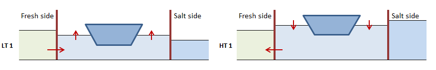
Schematic overview of leveling to the fresh side during low and high tide
The salt transport due to leveling at low tide (LT) can be described as:
Similarly for high tide:
By definition (see (10) and (11)) either \(V_{level,LT}\) or \(V_{level,HT}\) is zero, we can sum them up into one single equation:
When leveling at low tide, the average salinity of the water in lock chamber drops because fresh water is let in. To calculate this new salinity, we have to take into account the water displacement of ships present in the lock chamber:
In the situation around high tide, water is extracted from the lock chamber to lower the level, which does not change the salinity of the lock chamber:
With this, we can write (3) as follows:
(The salinity in the lock chamber after Phase 1, \(S_{L,S,Lev}\) can also be written as \(S_{L,1}\).)
The phase-averaged discharges to and withdrawals from the fresh side are then as follows (note that there are no flows on the salt side):
withdrawal from the fresh side, with the prevailing salinity \(S_F\):
discharge to the fresh side with salinity \(S_{L,S}\):
3.2. Phase 2: Door open on fresh side
The figure below illustrates that in principle there are no differences between low tide and high tide. In case of flushing through the lock, there is also a transport over the sea-side head.
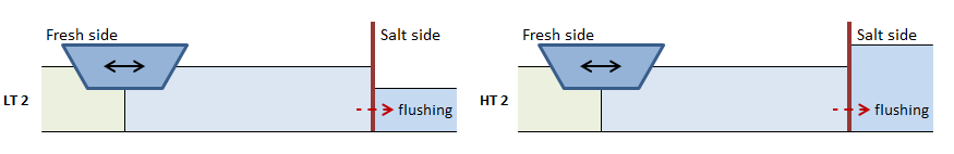
Schematic overview of flows when door is open on the fresh side during low and high tide
While the doors are open on one side there are various processes that take place that contribute to the transport of salt over the opened lock head. These processes are:
Salt transport due to ships exiting the lock chamber
Salt transports due to the lock exchange (with or without flushing)
Salt transport due to ships entering the lock chamber
If the transports due to these processes are independently calculated before adding them up, there is a possibility of the salt transport being too high. This would result in a salinity in the lock chamber that is lower than the fresh side, or higher than the salt side. To prevent this from happening, Phase 2 has been divided into three subphases, corresponding to the list above. Each of these subphases leads to a new intermediate salinity of the lock chamber:
1: Salt transport due to ships exiting the lock
Salt transport due to lock exchange (with or without flushing)
Contribution of lock exchange:
With \(V_{U,F}\) as determined in (20).
Contribution of flushing over fresh-side head:
Contribution of flushing over the salt-side head. When flushing for such a long time that the lock chamber’s salinity reaches that of the fresh side, the salinity of the water going to the sea side changes accordingly:
The new salinity at the end of this subphase then is:
Salt transport due to ships entering the lock
3.3. Phase 2: Total transports
The total transport of salt over the fresh-side head in this Phase is the sum of the transports of each subphase:
In case of a non-zero flushing discharge, there is also a transport over the salt-side head:
The resulting salinity in the lock is then:
(The salinity in the lock after Phase 2, \(S_{L,F}\), can also be written as \(S_{L,2}\).)
The phase-averaged discharges to and withdrawals from the fresh and salt side are then as follows:
withdrawal from the fresh side, with the prevailing salinity \(S_F\):
discharge to the fresh side with salinity \(S_{F,2}^+\):
there is no withdrawal from the salt side in this Phase
discharge to the salt side with average salinity \(S_S^+\)
3.4. Phase 3: Leveling to salt side
The leveling takes place on the sea-side head. There are no transports over the fresh-side head.
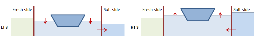
Schematic overview of leveling to the salt side during low and high tide
Just like in Phase LT 1 and HT 1 it holds that by definition either \(V_{level,LT}\) or \(V_{level,HT}\) is zero. Therefore we can sum the equations for both tidal phases up into a single one:
In the situation around low tide, water is extracted from the lock chamber to lower the level, which does not change the salinity of the lock chamber:
When leveling at high tide, the average salinity of the water in lock chamber rises because salt water is let in. To calculate this new salinity, we have to take into account the water displacement of ships present in the lock chamber:
With this, we can write (31) as follows:
(The salinity in the lock chamber after Phase 3, \(S_{L,F,Lev}\) can also be written as \(S_{L,3}\).)
The phase-averaged discharges to and withdrawals from the salt side are then as follows (note that there are no flows on the fresh side):
withdrawal from the salt side, with the prevailing salinity \(S_S\):
discharge to the salt side with salinity \(S_{L,F}\):
3.5. Phase 4: Door open on salt side
The figure below illustrates that in principle there are no differences between low tide and high tide. In case of flushing through the lock, there is also a transport over the fresh-side head.
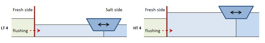
Schematic overview of flows when door is open on the salt side during low and high tide
While the doors are open on one side there are various processes that take place that contribute to the transport of salt over the opened lock head. These processes are:
Salt transport due to ships exiting the lock chamber
Salt transports due to the lock exchange (with or without flushing)
Salt transport due to ships entering the lock chamber
If the transports due to these processes are independently calculated before adding them up, there is a possibility of the salt transport being too high. This would result in a salinity in the lock chamber that is lower than the fresh side, or higher than the salt side. To prevent this from happening, Phase 4 (just like Phase 2) has been divided into three subphases, corresponding to the list above. Each of these subphases leads to a new intermediate salinity of the lock chamber:
1: Salt transport due to ships exiting the lock
Salt transport due to lock exchange (with or without flushing)
Contribution of lock exchange:
With \(V_{U,S}\) as determined in (29).
Contribution of flushing over fresh-side head:
Contribution of flushing over the salt-side head. When flushing for a long, an equilibrium situation arises as described in Section 2.6.2. Furthermore, the salinity of the flushing discharge going to the salt side changes from that of the (initial salinity of the) lock chamber to that of the fresh side.
The new salinity at the end of this subphase then is:
Salt transport due to ships entering the lock
3.6. Phase 4: Total transports
The total transport of salt over the salt-side head in this Phase is the sum of the transports of each subphase:
In case of a non-zero flushing discharge, there is also a transport over the fresh-side head:
The resulting salinity in the lock is then:
(The salinity in the lock after Phase 4, \(S_{L,S}\), can also be written as \(S_{L,4}\).)
The phase-averaged discharges to and withdrawals from the fresh and salt side are then as follows:
withdrawal from the salt side, with the prevailing salinity \(S_S\):
discharge to the salt side with salinity \(S_{S,4}^+\):
withdrawal from the fresh side, with the prevailing salinity \(S_F\):
there is no discharge to the lake side in this Phase